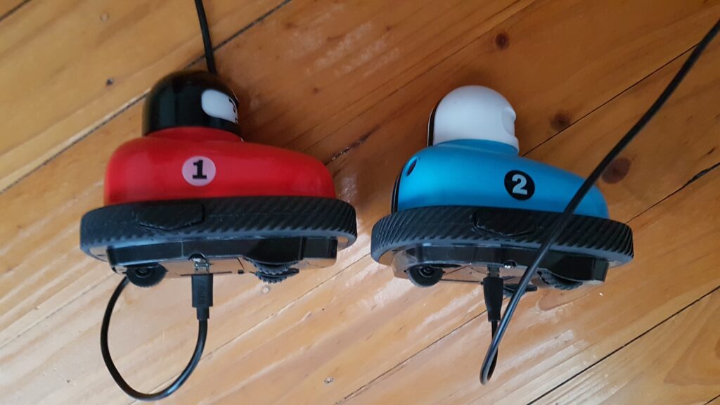
We want to demonstrate a great weekend project – a simple but rewarding conversation of a Remote Controlled Bumpy Car toy to work with recycled Li-Po rechargeable batteries by utilising the ITS01 battery charging module.
Tools needed
- Philips Screwdriver
- Solder iron and solder
- Drill with 1 mm and 2.5 mm drill bits
- Paper razor knife
- ITS01 – 1 Cell Li-Po Charger module with Battery Protection
- 18650 Rechargeable Battery – or any Li-On unprotected battery pouch
- Hot glue gun
- Multimeter
- Paper Tape (heat resistant Kapton Tape if available)
- 1m isolated wire to solder the battery, charging module
- Black marker pen
Video of the modification process
Introduction into battery operated toys
This set of Remote Controlled Bumpy Cars looked very entertaining. However, they needed 10 x AAA batteries in total—two for the Remote control and three for the car’s themselves.
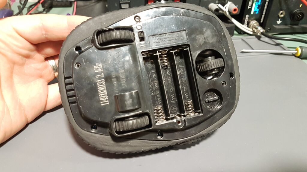
These RC Cars comes with a compartment for a standard AAA battery compartment at the bottom. However, it can hold AAA batteries, likely due to space limitation or engineering design. This device has two motors, each approx 3V @ 500mA, to run these wheels.
With the current setup, probably the whole car was pulling around 4.5V (3×1.5V) @ approx 1A when it runs on a carpeted floor. Generic AAA batteries have a power rating of approx 1A. This meant that, with three batteries, this toy runs for around an hour, which is pretty disappointing. At the high of the gameplay, batteries run out, causing me to stay on the side with a pack of replacement batteries like a pitstop.
Figuring out space restrictions and voltage requirements
The first step would be to take these toys apart to figure out how we can hack and integrate rechargeable battery within.
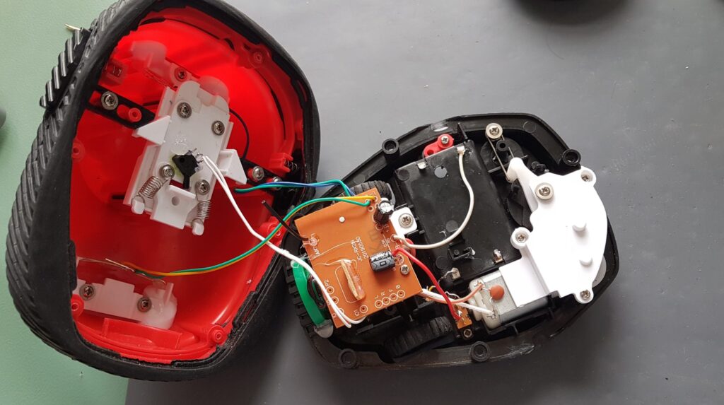
Inside we have white wire carrying ground from the battery pack terminals, while the red wire is passing voltage (4.5V) through switch to the controlling circuitry inside.
Implementing Rechargeable Battery Pack
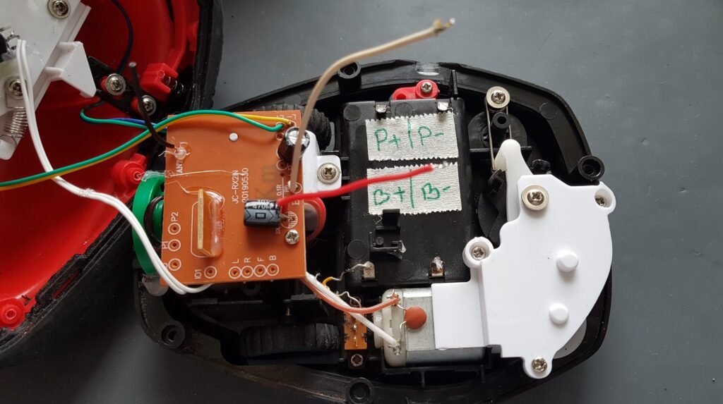
Let’s dig into the project. With opened case and located power input to the circuitry, we are ready to hijack the power lines and tap into the battery compartment. We want to make sure that we separate the charging circuitry from the internal electronics. This way, we have the micro USB connector available for quick charging without removing the battery cover.
The heart of this project is an ITS01 – 1 Cell Li-On Battery Charger with Protection. Ensuring Li-On cell is charged and discharged properly. Li-On (Li-Po) batteries are susceptible to a rapid charge/discharge and can easily catch fire. Hence, we need to ensure they have been looked after. At the same time, let’s not forget that this is a simple device that does not need much overlook and will be used for only a couple of hours and switched off for the rest of the time.
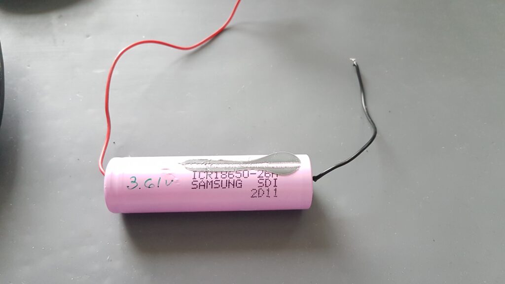
We needed a Li-On battery to power the toy. Due to the space restrictions and available cells we had, we used a 18650 single unprotected cell. Unprotected means that the cell does not have a protection circuit installed. Most of the shelf batteries that do not have a soldering terminal like this come with a charging/discharging protection.
While we could use any unprotected Li-On (Li-Po) battery for this project, we decided to use a recycled battery (like the ones coming from laptop battery packs). It is more environmentally friendly, and we could squeeze another year probably out of these batteries.
Once we have soldered the required wires to the 18650 battery cell terminals, we were ready to glue the cell battery.
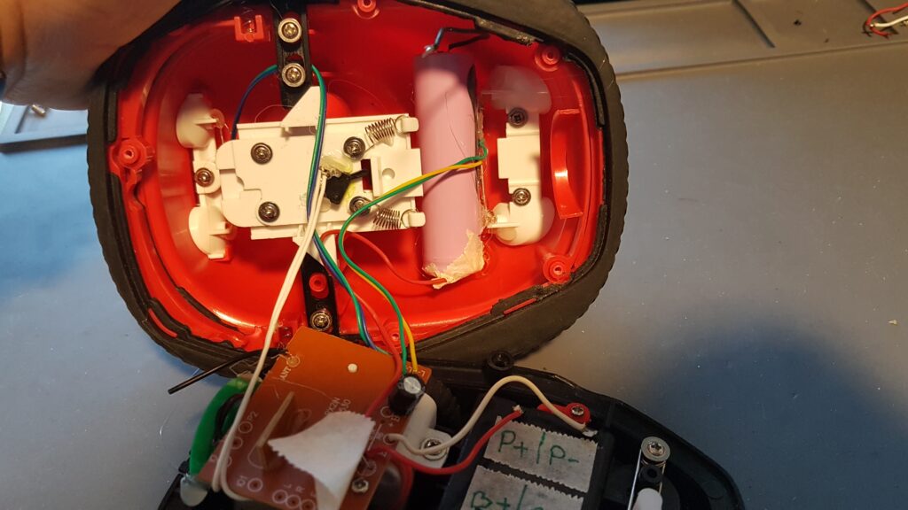
Two wires coming from the battery will get connected to the remaining two battery terminals on the case. We keep using the same terminals because we want easy access to the battery output and toy circuit input from within the ex-battery compartment.
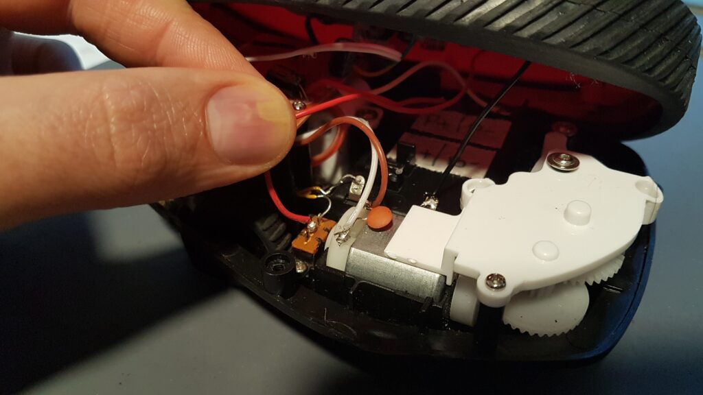
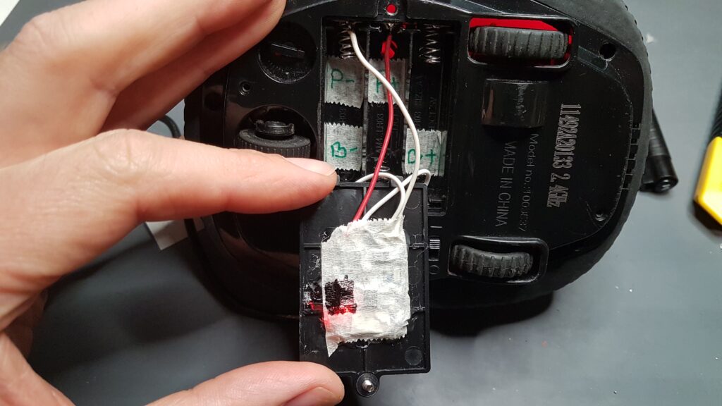
We solder the RED cable to the B+ terminal via the internal switch. At the same time, the BLACK cable from the battery went to B- terminal.
Running battery power through the internal switch is an important step. We do not want the battery to keep feeding the internal electronics while the toy is switched off. Additionally, these toys are a low-quality build, both electronic wise as well as hardware-wise. The last thing we want is a chip or the battery charging device to short the battery while the toy is not in use.
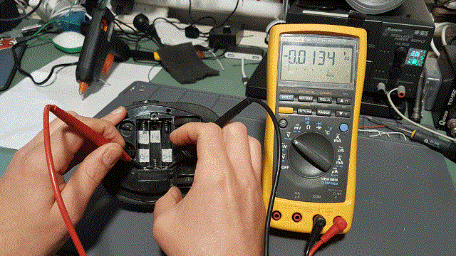
Next step to close the toy cover and measure if we get battery voltage on the B+ and B- terminals in the battery compartment. We won’t have any voltage on P+ and P- terminal yet, since the charging module is not installed.
NOTE: You need to ensure that you keep the labelling on the terminals. It is easy to forget where was the battery and where the power of the circuit, not to mention the polarity.
ITS01 Battery Charging module with Protection
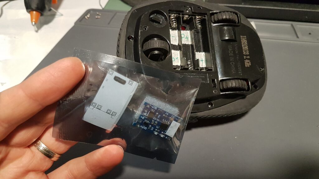
The project’s core is a small but effective 1 cell Li-Po charger – ITS01 battery charging module that comes with an integrated cell charge/discharge/short circuit protection. Which ensures the lithium cell is looked after while in use or charging.
Charging circuit fits nicely on the battery cover, thanks to its 90* turned micro-usb port. With little drilling on the cover and we can have easy access to charge the battery.
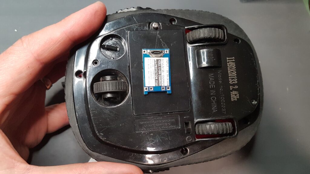
Preparing the battery cover to hold ITS01 battery charging module
The kit is available at our store and comes with easy to use guidance sticker of the pinouts and direction for easy marking of the place on the battery cover, which needs drilling.
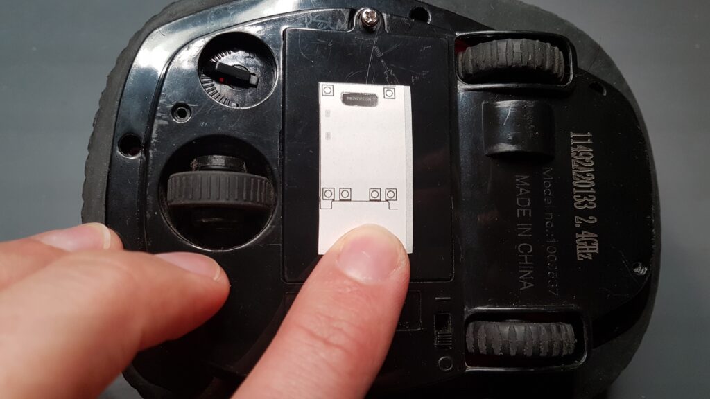
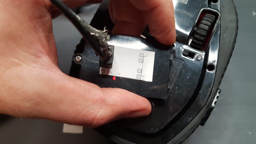
The guidance sticker can be applied to the battery cover and a 2.5mm drill can be used to create a micro-USB opening for the battery charger board.
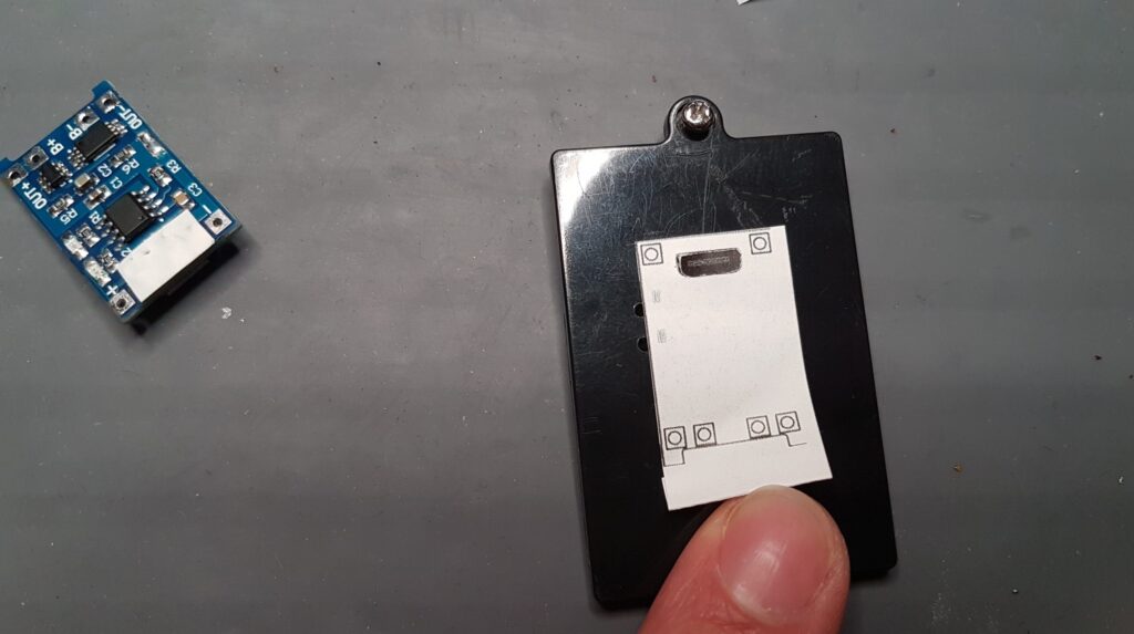
Once the guidance sticker is applied to the suitable location on the cover. It is easy to run a drill through it and create a opening for the micro-usb connector on the charging board.
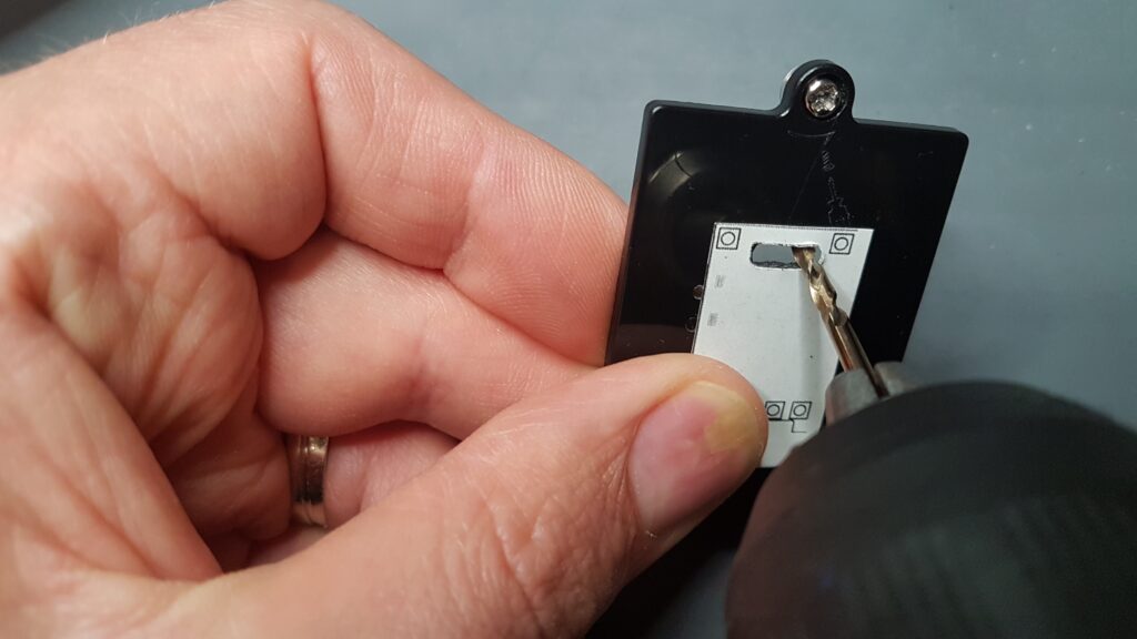
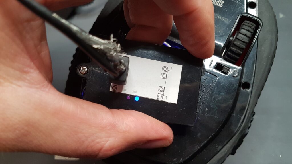
Afterwards, we also drill 2 small holes on the side of the sticker with 1mm drill bit, where the LED’s of the charging circuit are marked. This will allow us to reflect the battery charging LED (CHRG) and charging complete LED (RDY) outside of the cover.
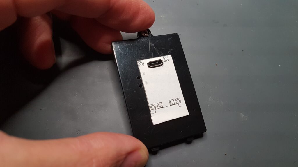
Finally, we position the charging board through the drill hole, and we are almost ready with the placing of the charging module.
Gluing the charging module
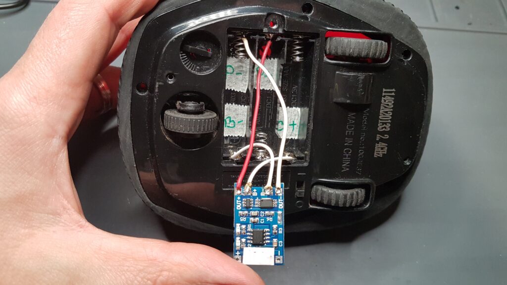
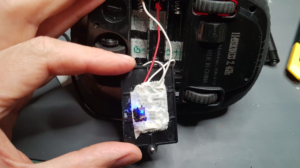
Before we glue the charging board to the battery cover, let’s solder the charging module to the battery terminals. Here we make use of the sticker markings we have used for battery terminals. We need to ensure that correct pinouts match the right terminals on the battery compartment.
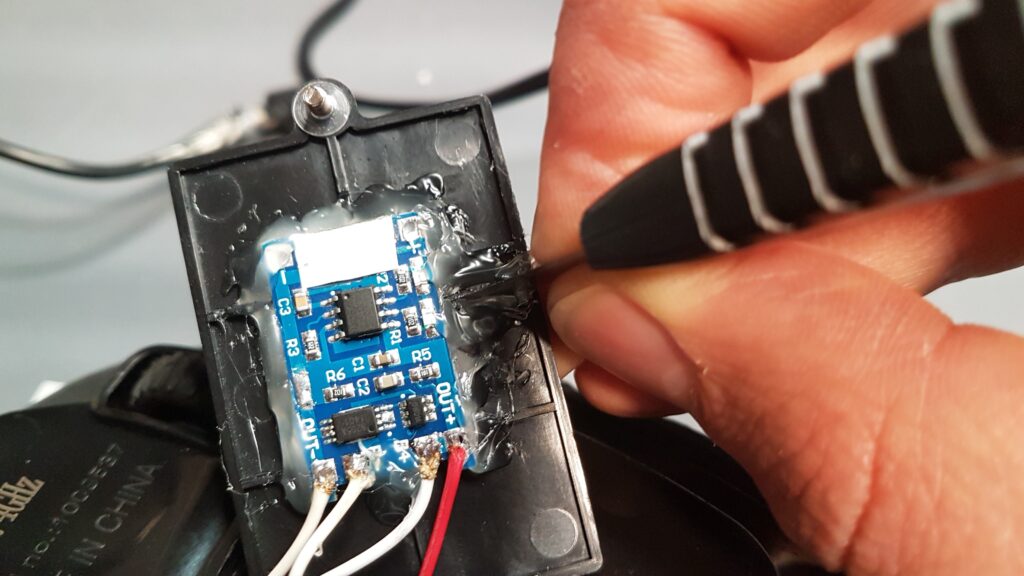
The last step is to secure the ITS01 Li-Po battery charging module to the battery cover with hot glue. We can either apply glue underneath the module and stick over it, or even better, apply glue around the corners and sides of the charging module. This should create a sturdy bond.
Do not forget to apply some hot glue through the LED 1mm holes on the side. The glue around the LED’s can easily reflect the light towards the LED light holes. A simple yet effective trick to redirect light.
We can use a razor knife to separate the glue between the LED’s while it is still hot. This is required as we will create a separation between the RED and BLUE LED. With a simple black marker, we can paint the gap between the glue applied around the LEDs, preventing mixing up RED and BLUE light.
Additionally we apply some paper tape (ideally kapton tape as this chip heats up while charging) on top to isolate any contacts with the battery compartment terminals.
Cutting out battery compartment separators
Now we need to ensure the battery cover fits nicely into the battery compartment, especially since we have the extra added charging module glued into there.
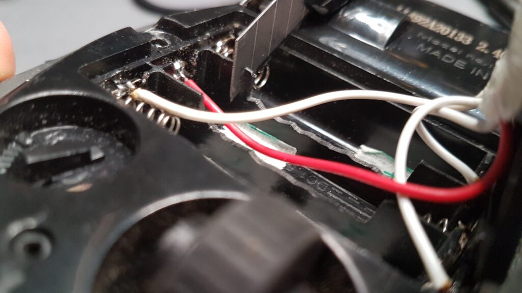
To ensure the snug fit, we need to cut out some of the segregations of the battery slots. We don’t plan to use any AAA batteries on this toy anymore to reduce the size and ensure the cover closes nicely. We can use our razor knife again to cut through the battery separations. Make sure you do not cut through cables or short terminals.
Before we close everything ensure that you get required voltage on the B+ and B- as well as on the P+ and P- terminals, when switched is turned on. We should get around 3.5V-4.2V there from the battery.
Final Result
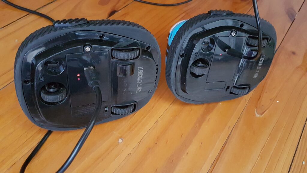
With the current low cost of toys and devices around us, one would ask why we bother. Well, this is a fun project and help us reuse recycled batteries as well as reduce the amount of single used batteries we disregard annually.
Perhaps the most valuable part of this project was the time I spent with my kid in modifications we did into it. Since we spent almost 2 hours modifying them together, even my 3-year-old had an attachment to these RC cars. And proudly tells everyone that we fixed them together.
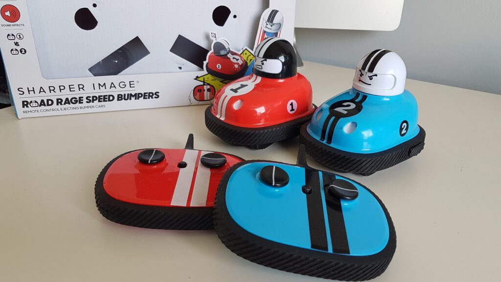
From a pile of Chinese cheap plastic toys, including RC toys, these are the only ones he plays with. After months of use, the batteries still performs great. What a great way to sustain our Planet and reduce the amount of plastic junk toys we throw away.
